 RSS Feed
 Twitter
motherboard
Labels: AT motherboard diagram , basic of motherbard , diagrams of motherboard , identify Components for Motherboard Upgrades , Iftekhar Ahmed Fahmi.cinema , Motherboard Diagram , 0 comments
 A computer motherboard diagram is very useful for when you need to replace motherboard, do motherboard upgrades, troubleshoot motherboard, or build your own computer.
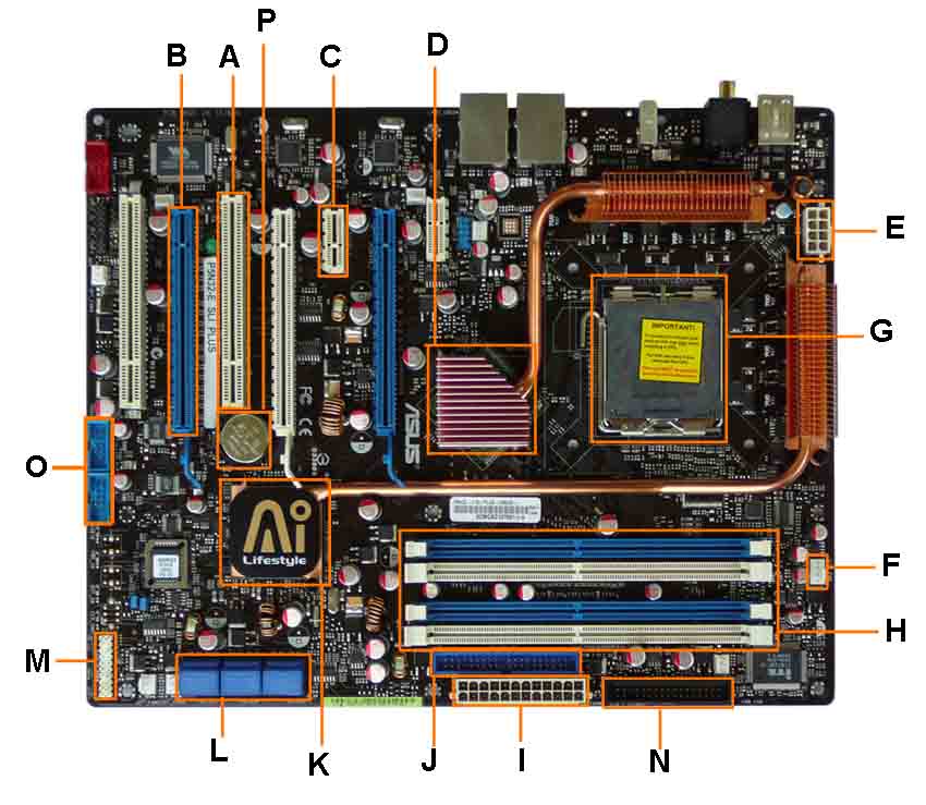
- PCI Slot - This board has 2 PCI slots. These two slots can be used for components such as cards, sods, modems, and Ethernet cards,
- PCI-E 16x Slot - There are 2 PCI-E 16x Slot on this motherboard diagram, both are in blue colour. These are used for your graphics card. With two of them onboard, you can run 2 graphics cards in SLI. It would be necessary only if you are a gamer, or working with high end video / graphics editing. These are the 16x speed versions, which are currently the fastest.
- PCI-E 1x Slot - These can be used for expansion cards such as Sound Cards, or Ethernet Cards.Single slot - In the PCIe 1.x generation, each lane (1x) carries 250 MB/s compared to 133 MB/s for the PCI slots.
- Northbridge - This is the Northbridge for this motherboard. This allows communication between the CPU and the system memory and PCI-E slots.
- ATX 12V 2X and 4 Pin Power Connection Power Connection - This is one of two power connections that supply power to the motherboard. This connection will come from your Power Supply.
- CPU-Fan Connection - This is where your CPU fan will connect. Using this connection over one from your power supply will allow the motherboard to control the speed of your fan, based on the CPU temperature.
- Socket - This is where your CPU will plug in. The orange bracket that is surrounding it is used for high end heat sinks. It helps to support the weight of the heat sink.
- Memory Slots - These are the slots for your RAM. Most boards will have 4 slots, but some will only have 2. The color coding you see on the motherboard diagram is used to match up RAM for Dual-Channel. Using them this way will give your memory a speed boost.
- ATX Power Connector - This is the second of two power connections. This is the main power connection for the motherboard, and comes from the Power Supply.
- IDE Connection - The IDE (Integrated Drive Electronics) is the connection for your hard drive or CD / DVD drive. Most drives today come with SATA connections, so you may not use this kind of device.
- Southbridge - This is the controller for components such as the PCI slots, onboard audio, and USB connections.
- SATA Connections - These are 4 of the 6 SATA connections on the motherboard. These will be used for hard drives, and CD / DVD drives etc.
- Front Panel Connections - This is where you will hook in the connections from your case. These are mostly the different lights on your case, such as power on, hard drive activity etc.
- FDD Connection - The FDD is the Floppy Disk controller. If you have a floppy disk drive in your computer, this is where you have hook it up.
- External USB Connections - This is where you will plug in external USB connections for your case or USB bracket.
- CMOS battery - This is the motherboard's battery. This is used to allow the CMOS to keep its settings flawless.
0 Response to "motherboard"
Post a Comment
Don't Forget to Thanks us !